| Load port map |
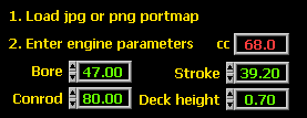
| Enter engine data |
| Rotate image |
| Trace ports |
| Check traces |
| Reference distances |
| Reference cursors |
| Port angles |
| Angle area graph |
| Port areas and power |
| Portmap measurements |
| Links |
The program can load a jpg, or png image. The data accuracy will depend on the pixs/mm
resolution of the image.
Use a positive deck height if the piston is below the top of the cylinder at TDC.
The bore diameter is used for calculating the horizontal resolution of the portmap image,
so it should not be changed after the horizontal pixels/mm have been calculated see below.
All other values can be changed at any time.
If the scanned portmap is not horizontal, you can turn on an alignment cursor to help
choose the correct rotation angle. The portmap can only be rotated before any ports
have been traced.
To rotate the portmap, after any ports have been traced, you must first erase all traces
using the 'Clear Traces' button.
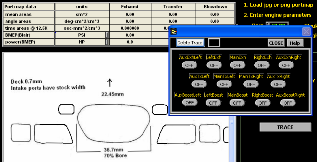
The 'Trace' button opens a keypad window with port names. In this case the main exhaust
port is about to be traced, so the 'MainExh' button is pressed. Notice the small black box
to the right of the 'Delete Trace' button. This is a color box that shows the color of the
pixel under the mouse. As you move the mose on the exhaust port outline, the color of this
box changes. To start a trace, move the mouse till the box color changes to the color of the
port ouline. In this case the port outline is black, so we want to click on the outline when
the color box is as dark as possible. Best places to start the trace is on the top, or bottom
of a port.
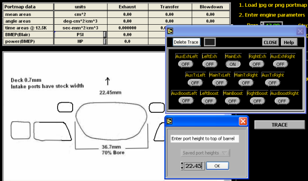
Before starting the trace, the program will prompt you for the port distance to the top of the
barrel. You can type in the distance or, if the same height has been used on another port,
select the height from the 'Saved port heights' drop down control.
If the trace wonders off the port outline, try darkening that section. If it wonders off on a
corner, try rounding the corner off slightly, or thicken the outline by adding a few dark pixels
on the inside of the corner.
If at any time you need to erase a trace, for example if you made a mistake in naming
a port, or the program traced incorrectly, just press the button with the same name as the
port you want to erase, and hit the 'Delete Trace' button.
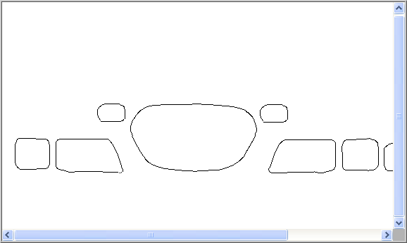
You can check the program's traces from menu->Traces->View traces.
Once the ports have been traced, the program knows the pixel location of the port outlines,
and the distance of each port from the top of the barrel. It must now convert the port's pixel
location to an absolute position in mm. To do this it needs to know the vertical and horizontal
resolution, in pixels/mm.
To calculate vertical pixs/mm you need to select 2 known vertical distances. You have the
option of using either one intake port roof, and one exhaust port roof, or, one intake port roof
and the top of the barrel. Note that the distances from the port roofs to top of barrel are known,
because they were entered when tracing the ports.
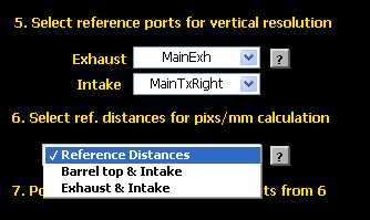
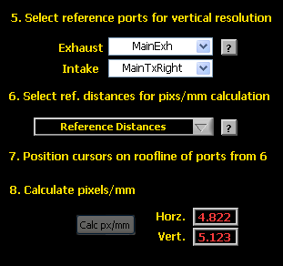
In the figure below you can see two drop down controls: one for exhaust, with a list of all exhaust
ports that have been traced, and one for intake, with a list of all traced transfer and boost ports.
Select the exhaust and intake ports whose distances to top of barrel you would like to use for
calculating pixs/mm. If you are going to use an intake port and top of barrel, you do not need to
select an exhaust port.

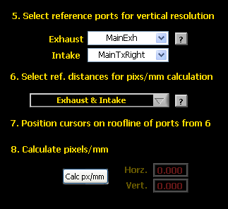
Now you tell the program which type of measurement will be used for calculating vertical
resolution. Select intake and exhaust heights, or intake height and barrel top, from the ref
distances drop down control. In this case we will use exhaust and intake distances, using
the ports that were selected above: main exhaust, and right main transfer.
The panel should now look like the figure below, with the "Calc px/mm" button enabled, ready
for you to position the image cursors.
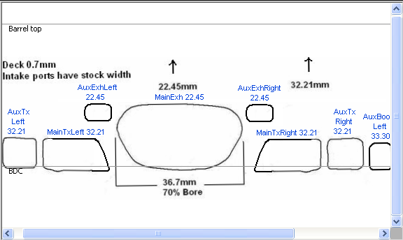
The portmap image is shown below with the reference cursors. The port names have been turned
on (menu->image text->show port names and heights) to make sure the cursors will be set on the
correct ports.
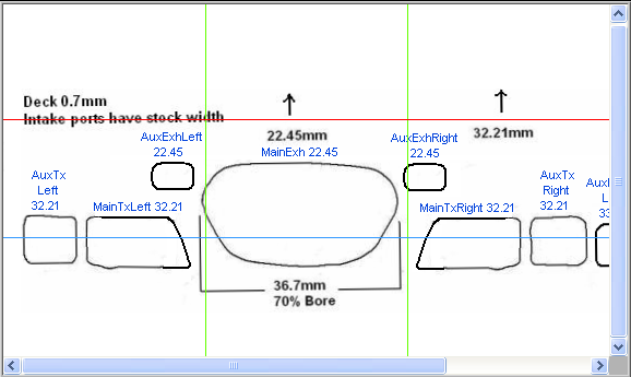
There are two horizontal cursors. The red cursor is for the exhaust, and will be positioned on
the top of the main exhaust. The blue cursor is for the intake, and will be positioned on the
right main transfer. The cursors must be positioned on the ports that were selected above (step 5.).
In this case the main and aux transfers are at the same height, so the intake cursor could be
placed on either one, as long as the heights are the same.
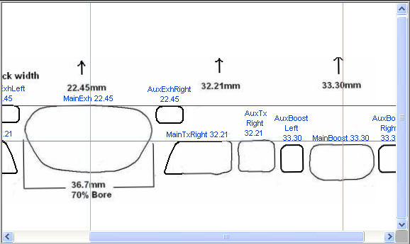
The vertical green cursors are used to set the reference horizontal distance. This distance is
always the bore size. One is set on the exhaust center, the other on the boost port center.
Note that if you change the engine's bore size, you must recalculate pixs/mm.
After positioning the cursors and hitting the Calc px/mm button, the resolution displays will
light up showing the calculated values:
The portmap image should look like this, with correctly positioned barrel top, and BDC cursors:
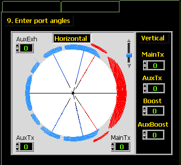
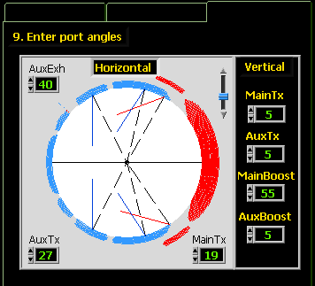
Port angles are referenced to a line between port center, and center of bore.
The last tab shows a picture of the bore, with controls to set the port angles.
On first opening, after setting pixs/mm, the image will need rotating to the position
shown below, with exhaust on the right, and boost on the left. Use the slider, with
knob, to rotate the image.
You can change the angles by clicking on the increment/decrement tabs, to the left
side of the controls. You can also type a value directly into the controls, but it may
not register till you mouse click on the main portmap image.
Open the angle are graph from menu->Tools->Time-Angle area graph.
The angle area graph shows the tranfers (blue) and exhaust (red) rpm ranges, based on the
angle areas from the data table. If you traced auxiliary exhaust, or boost ports, you can
turn these on/off to see their effect on the rpm ranges. You can also adjust the barrel height.
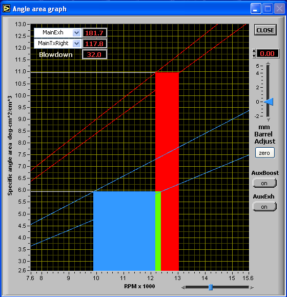
The straight reference lines represent fixed time areas in (sec-cm2)/cm3.
Exhaust : 0.00015 (upper red line), and 0.00014 (lower red line)
Tranfers: 0.00010 (upper blue line), and 0.0008 (lower blue line)
For an explanation of the fixed time area values (where they come from), and how the angle area
graph is derived from them for your engine, please see the article by Gordon Jennings (1).
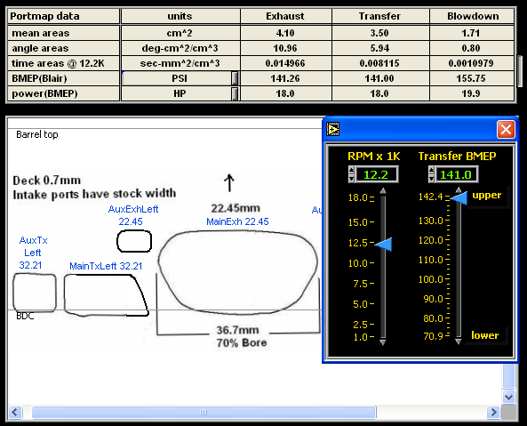
The top table displays total port areas, bmep and power. A small button, to the right of
the time area row, opens a small window with rpm and bmep controls. Here you can set the rpm
rpm value used to calculate the time areas, and choose the bmep setting for high or low case
compression.
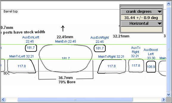
A portmap measurment tool is available from Menu->Tools->Portmap measurements. You can use this
to measure verical mm, vertical crank degrees, horizomtal mm, horizontal cord distance, and horizontal
percent of bore. There is one drop down menu for vertical measurement selection, and one for the
horizontal measurements. Both can be selected at the same time.
In the figure below, the vertical mesurement selector is set on crankshaft degrees. In this mode the
cursors are limited to between BDC and TDC.
A note on the measurements tolerances. You will note that, when measuring crank degrees, the error
increases as the cursor positions get closer to TDC or BDC. This is due to the vertical resolution being
equal to a larger value of crank degrees. To help reduce this error, while measuring a crank distance
relative to TDC or BDC, the following correction is made: If a cursor is positioned on TDC, the height
for that cursor is not calculated from its pixel position, but given the exact value of "stroke" mm above
BDC. This way one of the cursor errors can be set to zero, and the total error is reduced. The same
applies to a cursor positioned at BDC: its height is not calculated from the pixel position, but given the
exact value of 0 mm above BDC.
When measuring horizontal distances, cord or % bore, you will note that the error decreases as the
horizontal measure gets closer to the bore distance. This is due to the pixel location relative to the
curved surface of the bore. When the map (flat) distance is equal to the bore diameter, the small map
area, represented by an end pixel, is actually oriented perpendicular to the plane of the image (in and
out of the image). In this case the pixel's horizontal width error, now oriented perpendicular to the
measurement being taken, does not contribute to the measurement error.