Porting Calculator V4.2.1 |
All dimensions are in mm, unless stated differently on the front panel. Port heights refer to
the distance between port roof and top of barrel. Inputs are displayed in green, calculated
outputs are displayed in red.
Stock engine parameters are entered on the top row of controls.
Below the stock engine parameters are displays for input and output of porting information.
You can choose to have the program calculate either required port height adjustments, or
port durations. Position the red slide switch, located to the left of the displays, in line with
either the durations or 'raise port' displays. The selected displays will turn red, indicating
that they are now outputs. The unselected displays will turn green, indicating that they are
now inputs.
In either mode you can enter values for the exhaust, and main transfers by right mouse click
from the durations vs rpm graph. The graph is a plot of port durations vs rpm from
A.G.Bell's book: "Two-Stroke Performance Tuning".
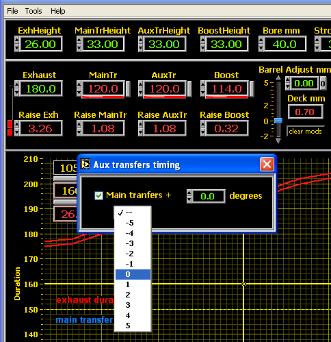
Each intake port can be locked to a fixed timing relation with the exhaust port. Main
tranfers can be fixed by blowdown time, aux. and boost ports can be fixed to the main
tranfer timing plus an offset in degrees.
Also available is a barrel height control. If the 'raise port' displays are set as outputs
('raise port' displays are red), the barrel can only be raised to the point where the raise
port values are positive or 0. You cannot raise the barrel past the point where a 'raise port'
value becomes negative.
The 'clear mods' button clears all porting mods, restoring the stock cylinder timing. Keep the
clear mods button pressed till all mods are cleared.
To the right of the barrel height control are the mean area displays. These show the required
mean port areas, given the current port timings and the rpm value of the graph cursor. A sliding
display, below the areas, can be set anywhere between the maximum and minimum intake port
timings. The calculation of required intake mean area will be based on this value.
Once the exhaust and tranfer heights have been calculated, the port cad window is used to
set the exhaust and tranfer port shapes. Exhaust shape controls allow the setting of roof
curvature in crank degrees, max width in percent of bore, and side curvature. Transfer port
controls allow the setting of port width and position. Mean exhaust and tranfer areas are
updated for each port while drawing. When done, the drawing can be saved as a png image,
and printed from Windows paint program. If the 'properties' menu item, in paint, show a resolution
of 96x96 pixels/inch, the image should print in actual size. This can be cut and used as a porting
guide.
Enter the stock engine specs in the top row of controls. When done, click on the 'Clear mods"
button, to the right of the barrel height control. This will clear the 'raise port' displays, and set
the correct port durations for the stock engine.
The red slider switch, on the left of the port displays, sets the program to calculate either
port height adjustments, or port durations. The displays selected as outputs will turn red, the
input displays will turn green.
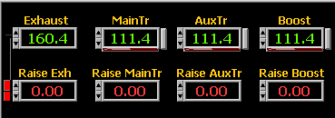
When set to calculate port height adjustments (fig 1), you enter the desired duration. Program
will use that duration, together with stock cylinder specs and barrel height setting, to calculate
the required change in port height.
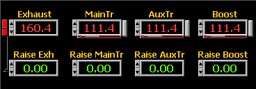
When set to calculate duration (fig 2), you enter the port height adjustments. The program
calculates the new durations based on the port height adjustments, stock cylinder specs, and
barrel height. Use this mode if you would like to see the effect of crank size, or rod length
changes on the port durations.
Open the intake port's setup window by clicking on the button to the right of its duration
display (they do not all have to be set up together). Each intake port's timing can be fixed
to a timing relation. The main transfer timing can be fixed to a blowdown time, and the aux
and boost ports can be fixed to an offset timing from the main tranfers.
In this example, with all intake ports fixed and mode switch set to calculate port height
adjustments, the only port parameter left free is the exhaust duration. Type in the duration
(eg 180), and the program calculates all the other variables. You can change the barrel
height or any engine parameter, the exhaust duration will stay at 180, while everything else
is adjusted automatically. In this example, the barrel height adjustment will be limited to
+0.32mm, which is the maximum before the 'raise boost' value would become negative.
Raise barrel control
The range of the raise barrel control is set by the stroke:
Lower limit is from -2mm at 39.2mm stroke, to -5mm for 99mm stroke
Upper limit is 5mm at 39,2mm stroke, to 12.6mm for 99mm stroke
The slider adjusts barrel height in approx 0.1mm increments. For 0.01mm increments
you can click on the small arrows at the ends of the slider. To clear the slider to exactly
zero, use the '0' button to the right of the slider digital display.
Port durations, for exhaust and main transfers, can be entered directly from the
graph. Set graph cursor on desired duration for exhaust port, and right click mouse.
You can fine adjust the cursor position with the buttons underneath graph's duration
display. Repeat for main transfer timing (unless main transfer duration is already
specified by blow-down time). Duration values above 150 degrees will set the exhaust
port, below 150 the main transfer.
If you select main transfer and exhaust durations at the same rpm, the rpm will be
recorded and saved as 'Port height based rpm'. The rpm display background will turn
light green. This feature was included in case the port durations are set from Bell's
duration vs rpm data lines. The 'Port height based rpm' label, in the data file, will
be a reminder that the durations were set using Bell's data.
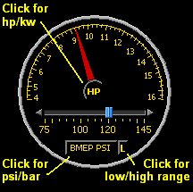
Calculates hp from your expected bmep value. The bmep value is also used to calculate
the Blair port areas. You can change bmep units between psi and bar, and power units
between hp and kw. A high low range button switches BMEP ranges between 75-145psi
(~5-10bar), and 145-215psi (~10-15bar).
You can switch between Jennings port areas, or Blair. When using Blair areas, you can
set the bmep value on the power meter. When using Jennings areas, the tranfer min-max
range is a guideline to stay within. For blair areas the min tranfer value corresponds
to low case compression, the max value to high case compression. In this case the min area
value will be higher than the max. The total port areas are an approximation, assuming
that mean areas are approximately 0.7 times total area.
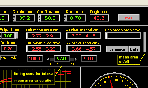
If boost port duration is different from transfer duration, you can select the intake duration
used to calculate transfer mean area. Transfer mean area is based on the sliding green display
(figure 6), which can be adjusted from left (transfer duration) to right (boost duration).
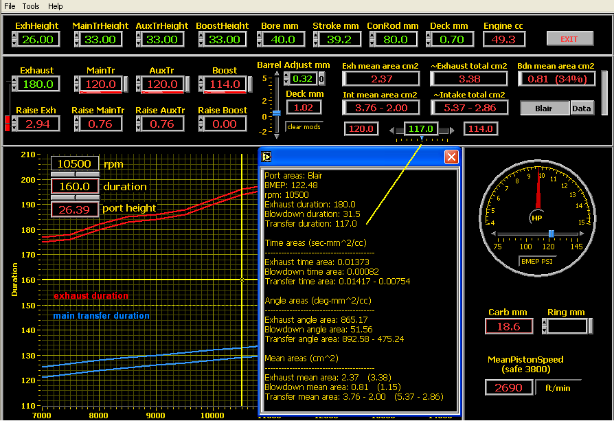
The 'Data' button opens up a window with all the area data. Figure 7 shows the data window for
Blair port areas. Note the transfer duration used is from the sliding display. Data values in parenthesis
are approximate total cord areas.
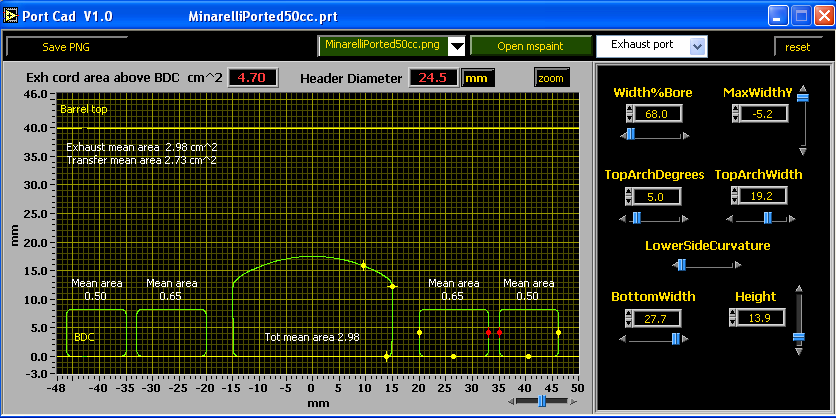
Open the port cad window by selecting Tools->Port cad from the main menu.
Ports roof distances, from top of barrel, are fixed by the settings in the main program’s window.
In the cad window ( figure 5) you can adjust the port shapes for the target mean areas.
The zoom button toggles the drawing to full cylinder height view, showing the location of the
top of the barrel.
Header diameter is the exhaust flange outlet diameter. This gives the same area as the exhaust
port’s total cord area above bottom dead center.
Use the port name drop-down menu to select the shape controls for a given port. You can also
change a port's shape by dragging its cursors. Yellow cursor dots change the port's shape,
red cursors change the port's position.
The reset button restores the port controls to the values in the data file (loaded from the menu
in the main window), or to default values if a data file has not yet been saved.
At any point you can use the 'Save PNG' button to save a png image of the ports. All png files,
saved in the current session, will appear in the drop-down selector by the 'Open mspaint' button.
Open mspaint is disabled until there is at least one entry in the png file drop-down selector.
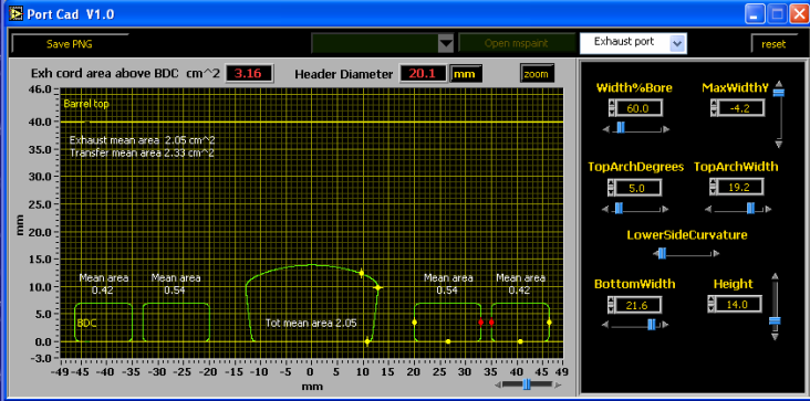
- Max port width in % of bore
Sets exhaust width - MaxWidthY
Height of max width point below roof of port - TopArchDegrees
Curvature of top arch segment in crank degrees - TopArchWidth
Width of top arch segment - LowerSideCurvature
Curvature of bottom left and right sides - BottomWidth
- Height
Ehter the stock port height here. Does not include distance that port is raised.
Total exhaust height will be Height + RaiseExh control in main window.
Refer to figure 9 below for the definition of horizontal distances. Port position is the distance
between left and right ports. The red port cursors mark the reference point for the position
measurement. To change port position you can drag the red cursor, or change the value in the
position control. The port will move, keeping the width constant. Change the port width by
dragging the yellow cursor, or entering a value in the port width control.
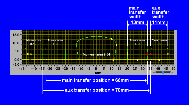
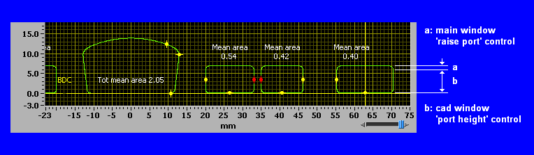
Figure 10 below shows how the port heights are defined. The CAD port height control should
be set to the port's stock height (port top to port bottom). The total port height will be the CAD
port height control, plus the 'raise port' value in the main window. The exhaust port height is
defined in the same way.
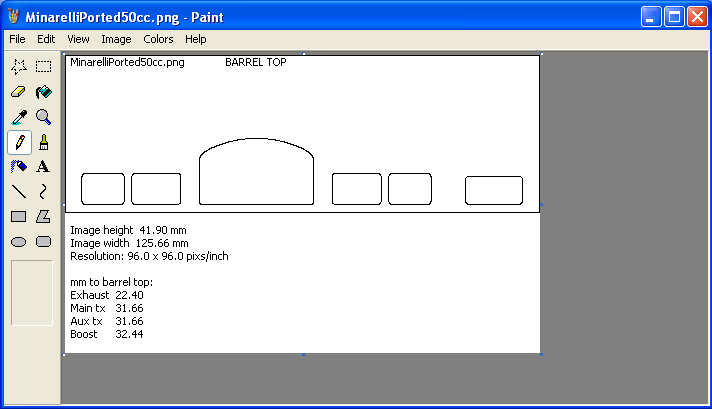
Once your port shapes are finished, you can choose the resolution for the printable png portmap
image. After pressing "Save PNG" an image resolution prompt window appears with a selection
of resolutions (pixels/inch): 96, 150, 200, 300, and other. If you select 'other', you can manualy
enter any resolution between 96 and 600.
Choosing 96 pixs/inch should allow you to print the portmap image in actual size, using mspaint.
The higher resolutions will give finer port outlines, but you must have photo software that will
allow you to print in actual size. You can print the image on transparancy film to use as a porting
guide.
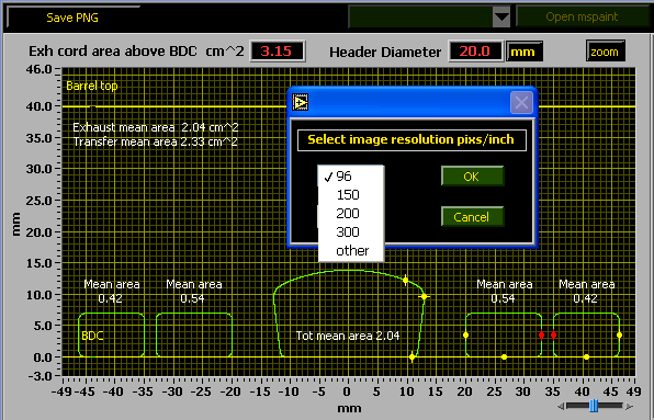
Figure 12 shows the png file controls after at least one image has been saved. You can save multiple png
maps. The name of each png file, saved in the current session, will appear in the drop down list to the right
of the save png button. Once there is at least one file name in the list, the 'Open mspaint' button will be
activated. This will open the selected file in mspaint.
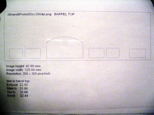
The printed image has a one pixel thick black border. This is part of the barrel image, so cuts need to be
made on the outside of the border. The cutout dimensions, given by ‘Image height’ and ‘Image width’, as
well as all port heights to top of barrel, are printed under the portmap image. Fig 13 shows a 96 pixs/inch
portmap image opened in mspaint. Fig 14 shows a pixs/inch (dpi) printed actual size on a transparency.